18 Triangulation Algorithms for 2D Positioning (also known as the Resection Problem): benchmarking, software, source code in C, and documentation
Vincent Pierlot and Marc Van Droogenbroeck,
Montefiore Research Institute, University of Liège, Belgium
1 Benchmarks
| Algorithm | + | × | ⁄ | √(x) | trigo | time (s) † | Command line | |
| [14, 15] | ToTal 1 | 30 | 17 | 2 | 0 | 2 | 0.163 | ./triangulation -t3 -n1000000 -m1 |
| [11] | Ligas 1 | 29 | 22 | 2 | 0 | 2 | 0.171 | ./triangulation -t3 -n1000000 -m18 |
| [7] | Font-Llagunes 1 | 23 | 17 | 2 | 0 | 5 | 0.223 | ./triangulation -t3 -n1000000 -m3 |
| [12] | Cassini 2 | 19 | 8 | 3 | 0 | 4 | 0.249 | ./triangulation -t3 -n1000000 -m22 |
| [2] | Cohen 1 | 37 | 15 | 3 | 2 | 4 | 0.272 | ./triangulation -t3 -n1000000 -m10 |
| [1] | Easton 2 | 22 | 24 | 1 | 0 | 5 | 0.298 | ./triangulation -t3 -n1000000 -m7 |
| [4] | McGillem 1 | 37 | 18 | 5 | 2 | 8 | 0.340 | ./triangulation -t3 -n1000000 -m6 |
| [6] | Hmam 2 | 29 | 11 | 3 | 3 | 9 | 0.428 | ./triangulation -t3 -n1000000 -m8 |
| [2] | Cohen 2 | 26 | 11 | 3 | 2 | 11 | 0.437 | ./triangulation -t3 -n1000000 -m9 |
| [10] | Esteves 2 | 43 | 14 | 2 | 2 | 11 | 0.471 | ./triangulation -t3 -n1000000 -m2 |
| [12] | Collins 2 | 34 | 10 | 2 | 2 | 11 | 0.485 | ./triangulation -t3 -n1000000 -m21 |
| [4] | McGillem 2 | 29 | 9 | 3 | 2 | 11 | 0.501 | ./triangulation -t3 -n1000000 -m5 |
| [12] | Kaestner 2 | 28 | 10 | 3 | 2 | 11 | 0.504 | ./triangulation -t3 -n1000000 -m20 |
| [13] | Tsukiyama 1 | 52 | 22 | 3 | 5 | 14 | 0.596 | ./triangulation -t3 -n1000000 -m12 |
| [5] | Casanova 1 | 52 | 21 | 4 | 5 | 14 | 0.609 | ./triangulation -t3 -n1000000 -m4 |
| [9] | Tienstra 2 | 33 | 18 | 8 | 3 | 9 | 0.640 | ./triangulation -t3 -n1000000 -m17 |
| [8] | Font-Llagunes 1 | 62 | 25 | 6 | 1 | 8 | 0.648 | ./triangulation -t3 -n1000000 -m19 |
| [3] | Madsen 2 | 38 | 24 | 5 | 3 | 15 | 0.707 | ./triangulation -t3 -n1000000 -m14 |
2 Programs
2.1 Download the C source code (zip package)
2.2 Run the program by yourself
./triangulation
2.3 Compile the code by yourself.
2.4 Options when you run the program
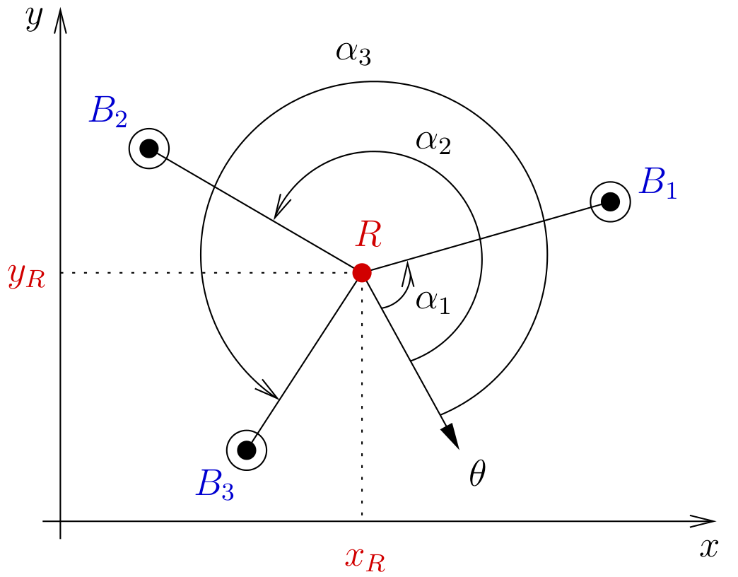
3 ToTal Algorithm
3.1 Description
-
compute the modified beacon coordinates:
x’1 = x1 − x2, y’1 = y1 − y2, x’3 = x3 − x2, y’3 = y3 − y2, -
compute the three cot(.):
T12 = cot(α2 − α1), T23 = cot(α3 − α2), T31 = (1 − T12T23)/(T12 + T23) -
compute the modified circle center coordinates:
x’12 = x’1 + T12 y’1, y’12 = y’1 − T12 x’1,
x’23 = x’3 − T23 y’3, y’23 = y’3 + T23 x’3,
x’31 = (x’3 + x’1) + T31 (y’3 − y’1),
y’31 = (y’3 + y’1) − T31 (x’3 − x’1), -
compute k’31:
k’31 = x’1x’3 + y’1y’3 + T31(x’1y’3 − x’3y’1), -
compute D (if D = 0, return with an error):
D = (x’12 − x’23)(y’23 − y’31) − (y’12 − y’23)(x’23 − x’31), -
compute the robot position {xR, yR} and return:
xR = x2 + (k’31(y’12 − y’23))/(D), yR = y2 + (k’31(x’23 − x’12))/(D).
3.2 The ToTal algorithm in C code
3.3 The ToTal algorithm in Matlab/Octave code
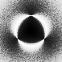
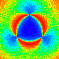
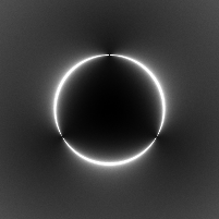
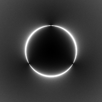
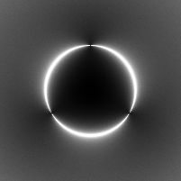
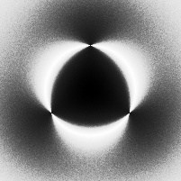
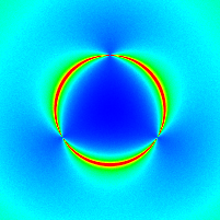
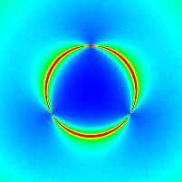
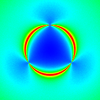
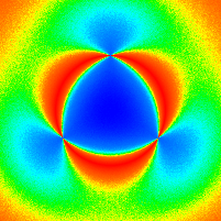
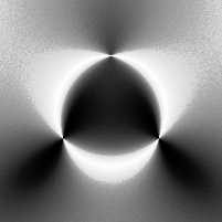
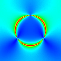
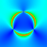
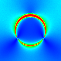
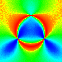
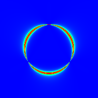
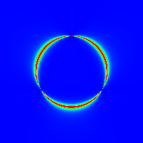
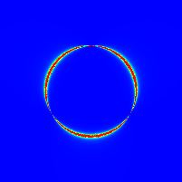
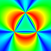
4 Simulations
|
|
|
|
|
|
|
|
| ./triangulation -t5 -M4 -s"0.01" -T1 -n1000 | ./triangulation -t5 -M4 -s"0.1" -T1 -n1000 | ./triangulation -t5 -M4 -s"1.0" -T1 -n1000 | ./triangulation -t5 -M2 -s"0.1" -T1 -n1000 |

|

|

|
|
|
|
|
|
| ./triangulation -t5 -M4 -s"0.01" -T2 -n1000 | ./triangulation -t5 -M4 -s"0.1" -T2 -n1000 | ./triangulation -t5 -M4 -s"1.0" -T2 -n1000 | ./triangulation -t5 -M2 -s"0.1" -T2 -n1000 |

|

|

|

|
|
|
|
|
| ./triangulation -t5 -M4 -s"0.01" -T3 -n1000 | ./triangulation -t5 -M4 -s"0.1" -T3 -n1000 | ./triangulation -t5 -M4 -s"1.0" -T3 -n1000 | ./triangulation -t5 -M2 -s"0.1" -T3 -n1000 |
5 Copyrights and license
References
[1] . A Gaussian Error Model for Triangulation-Based Pose Estimation Using Noisy Landmarks. IEEE Conference on Robotics, Automation and Mechatronics:1-6, 2006. URL http://dx.doi.org/10.1109/RAMECH.2006.252663.
[2] . A Comprehensive Study of Three Object Triangulation. Mobile Robots VII, 1831:95-106, 1992. URL http://dx.doi.org/10.1117/12.143782.
[3] . Optimal landmark selection for triangulation of robot position. Robotics and Autonomous Systems, 23(4):277-292, 1998. URL http://dx.doi.org/10.1016/S0921-8890(98)00014-1.
[4] . A Beacon Navigation Method for Autonomous Vehicles. IEEE Transactions on Vehicular Technology, 38(3):132-139, 1989. URL http://dx.doi.org/10.1109/25.45466.
[5] . A New Beacon-based System for the Localization of Moving Objects. IEEE International Conference on Mechatronics and Machine Vision in Practice, 2002. URL http://citeseerx.ist.psu.edu/viewdoc/summary?doi=10.1.1.7.1615.
[6] . Mobile Platform Self-Localization. Information, Decision and Control:242-247, 2007. URL http://dx.doi.org/10.1109/IDC.2007.374557.
[7] . Consistent triangulation for mobile robot localization using discontinuous angular measurements. Robotics and Autonomous Systems, 57(9):931-942, 2009. URL http://dx.doi.org/10.1016/j.robot.2009.06.001.
[8] . New method that solves the three-point resection problem using straight lines intersection. Journal of Surveying Engineering, 135(2):39-45, 2009. URL http://dx.doi.org/10.1061/(ASCE)0733-9453(2009)135:2(39).
[9] . Simple Solution to the Three Point Resection Problem. Journal of Surveying Engineering, 135(4):170-172, 2009. URL http://dx.doi.org/10.1061/(ASCE)0733-9453(2009)135:4(170).
[10] . Position and Orientation Errors in Mobile Robot Absolute Self-Localization Using an Improved Version of the Generalized Geometric Triangulation Algorithm. IEEE International Conference on Industrial Technology (ICIT):830-835, 2006. URL http://dx.doi.org/10.1109/ICIT.2006.372345.
[11] . Simple Solution to the Three Point Resection Problem. Journal of Surveying Engineering, 139(3):120-125, 2013. URL http://dx.doi.org/10.1061/(ASCE)SU.1943-5428.0000104.
[12] . Three point resection problem. Surveying Engineering Department, Ferris State University, 2005.
[13] . Mobile Robot Localization from Landmark Bearings. World Congress on Fundamental and Applied Metrology:2109-2112, 2009. URL http://www.imeko.org/publications/wc-2009/IMEKO-WC-2009-TC17-084.pdf.
[14] . A new three object triangulation algorithm based on the power center of three circles. Research and Education in Robotics (EUROBOT), 161:248-262, 2011. URL http://hdl.handle.net/2268/89435.
[15] . A New Three Object Triangulation Algorithm for Mobile Robot Positioning. IEEE Transactions on Robotics, 30(3):566-577, 2014. URL http://dx.doi.org/10.1109/TRO.2013.2294061.
[16] . BeAMS: a Beacon based Angle Measurement Sensor for mobile robot positioning. IEEE Transactions on Robotics, 30(3):533-549, 2014. URL http://dx.doi.org/10.1109/TRO.2013.2293834.